Electronic irrigation controller based on PIC
version 1, 2001/07/06designed by Peter JAKAB
NOTE for beginners: PICs are general purpose microcontrollers which have to be programmed before you can use them in the actual circuit! Check out this link to learn more.
description
This is a simple one-valve irrigation controller made for our greenhouse. The code contains a software real-time clock (RTC) and a multiplexed 8-digit LED display and keyboard you can use in other projects.software, operation
The operating software is simple, it contains a real-time clock and a day counter. The valve is turned on in regular intervals in the same time. Day setting specifies the number of days between the activations, time setting specifies the time of the day when to start. Duration is the time after which the valve will be turned off.- MODE button cycles through clock, start time and duration settings
- the interval and starting time set will be stored in the DATA EEPROM
- Scheduling can be totally turned OFF by the ENABLE button
- Irrigation can be manually turned ON/OFF any time by the START/STOP buttons
- Activation/STOP time is displayed in the second line of display
- Valve state (ON/OFF) is displayed in the second line, last dot
schematic diagram
click to zoom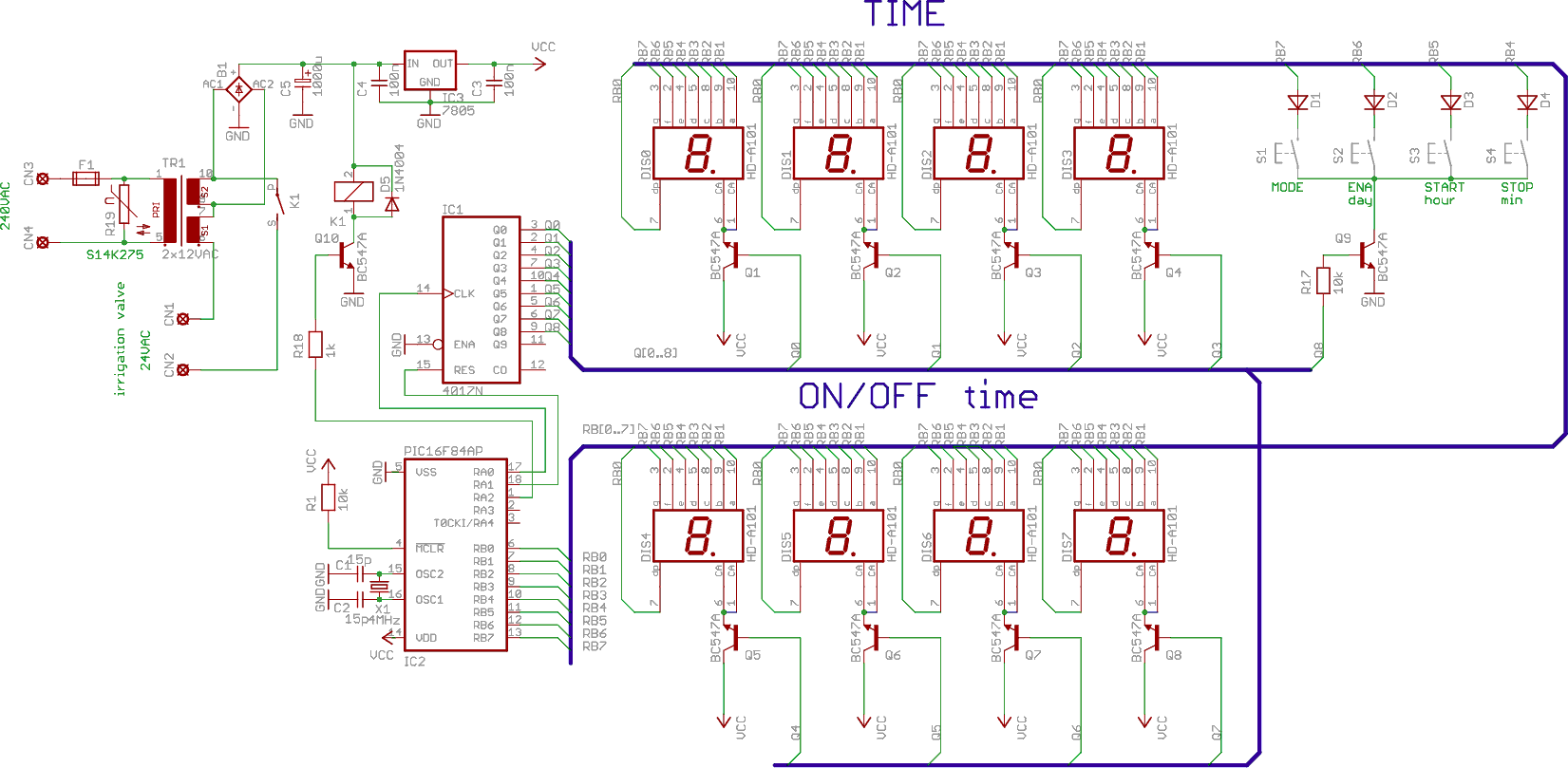
components
| name | value |
| DIS0-DIS7 | common-anode 8x1-digit or 4x2-digit 7-segment LED display |
| TR1 | mains transformer, 1x220VAC, 2x12VAC |
| - | 24VAC irrigation valve |
| K1 | 12VDC relay. Contacts: >=1A |
| Q1-Q10 | 10xBC547A or similar NPN bipolar transistor |
| IC1 | CD4017N |
| IC2 | PIC16F84 or PIC16F84A microcontroller, programmed |
| IC3 | 7805 voltage regulator with heatsink |
| AC1 | diode bridge at least 80V/1A |
| X1 | 4MHz crystal |
| R1, R17 | 2x10k |
| R18 | 1k |
| R19 | S14K275 varistor |
| C1, C2 | 2x15pF |
| C3, C4 | 2x100nF |
| C5 | 1000uF/25VDC |
| D1-D4 | 4x1N4148 |
| S1-S4 | 4xpush buttons |
| CN1-CN4 | connector |
| F1 | fuse 0.1A T |
| misc | PCB, housing |


0 comments: